Injection molding is one of the most reliable ways to manufacture repeatable plastic parts. A two-part mold is the most common mold type because it is simple, scalable, and compatible with many tooling methods. This guide explains how to design a two-part injection mold, how to choose a parting plane, how to avoid undercuts, and how to add draft, sprues, vents, and flow considerations.
If you have searched for questions like how to make an injection mold, two-part mold design, parting line injection molding, or how to create a mold from an STL file, this article will walk you through the full process in a practical way.
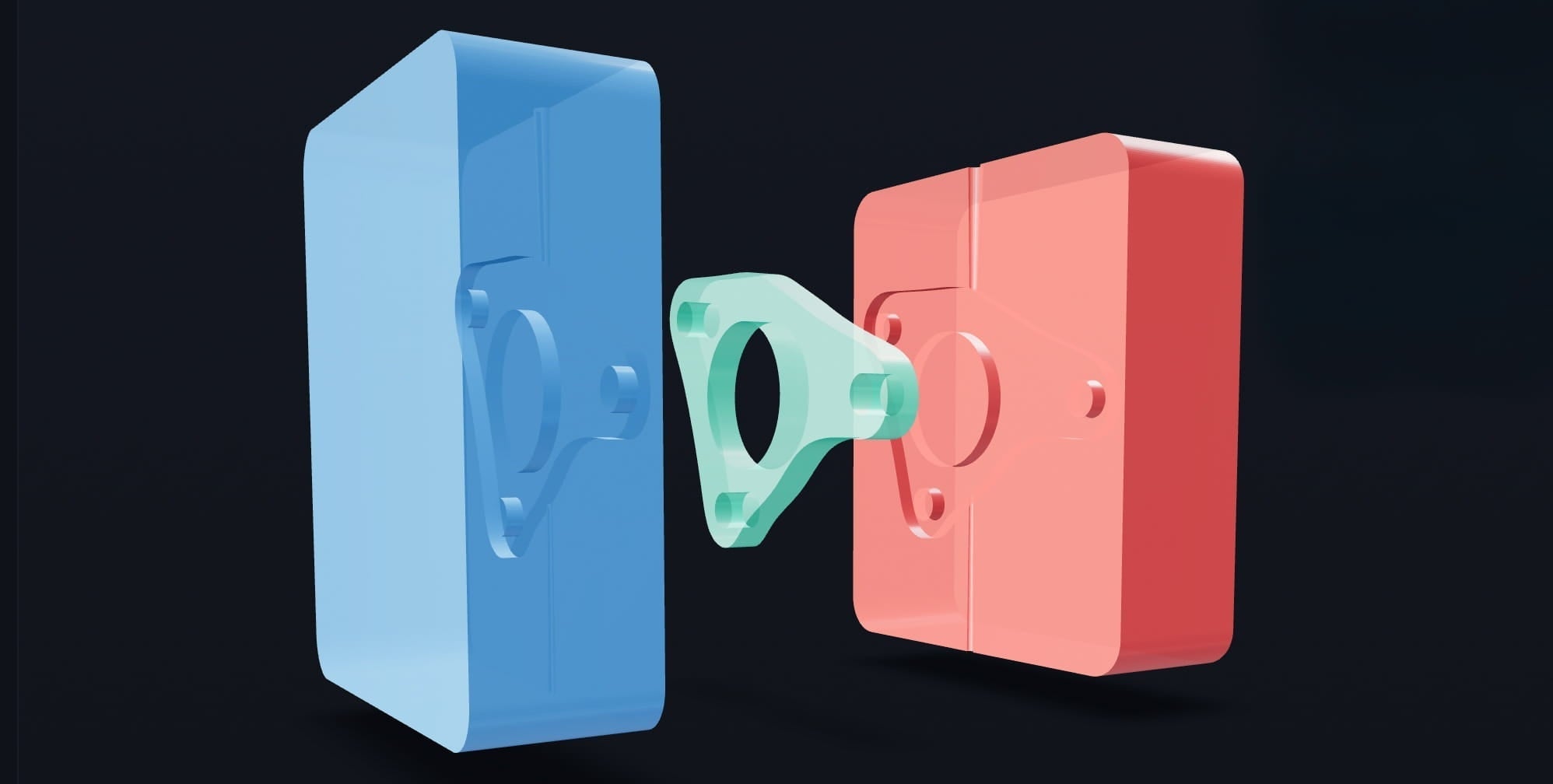
What is a two-part injection mold?
A two-part injection mold is a mold made of two halves that close together to form the cavity of your final part. The two halves are typically called:
- Cavity: forms the outside surface of the part
- Core: forms internal features and opposing geometry
Two-part molds are the most common starting point in injection mold design because they are mechanically simple and can produce highly consistent parts when the geometry is demoldable.

How does a two-part mold work?
- The mold closes, aligning the core and cavity.
- Molten plastic enters through the sprue (and gate region).
- The plastic fills the cavity and pushes air out through vents.
- The plastic cools and solidifies inside the mold.
- The mold opens and the part is removed.
Most injection molding defects trace back to one of three causes: poor parting plane selection, insufficient draft, or poor air escape and flow behavior. Designing around these early makes molding dramatically easier.
Step 1: How to choose the correct parting plane
The parting plane is the plane where the two mold halves separate. Choosing the best parting direction and split location is the most important step in two-part mold design.
What makes a good parting plane?
- The part can release straight out of the mold in the opening direction.
- Undercuts are minimized or eliminated.
- The seam line is placed in less-visible areas when possible.
- The split avoids floating sections and trapped geometry.
Practical tip
If you are unsure, rotate the part and evaluate multiple candidate split directions. Many parts become moldable simply by changing orientation.

Step 2: What are undercuts in injection molding?
An undercut is any feature that prevents a part from being pulled straight out of the mold in the chosen opening direction. Undercuts can lock a part into the mold and make demolding impossible with a simple two-part tool.
Common undercut examples
- Reverse hooks and snap features
- Side-facing openings or holes
- Overhangs that oppose the mold opening direction
Industrial molds can use sliders or lifters to handle undercuts, but for simple two-part molds, the easiest and most reliable approach is to remove undercuts by design changes or by changing the part orientation and parting direction.
Step 3: Draft angles explained (how much draft do you need?)
A draft angle is a small taper on vertical walls that helps the part release from the mold. Draft reduces friction, prevents scuffing, and dramatically improves demolding reliability.
Draft angle guidelines
- 1 to 2 degrees is a common guideline for many plastics.
- Use more draft for textured surfaces.
- Some geometries and materials benefit from additional draft.
Without draft, parts may stick, deform during removal, or require excessive force to eject. Draft analysis is one of the fastest ways to identify moldability issues before making tooling.

Step 4: Sprues, gates, and venting
A mold needs more than the core and cavity shape. It must also deliver plastic to the cavity and allow air to escape.
What is a sprue?
The sprue is the main channel that carries molten plastic into the mold. Where you place the sprue impacts filling, surface finish, internal stresses, and cycle consistency.
Why venting matters
As the plastic fills the cavity, it must push air out. Vent channels let air escape while preventing plastic from leaking out. Poor venting can cause short shots, bubbles, and burn marks.
Step 5: Why plastic flow simulation helps
Plastic does not fill evenly. Wall thickness, flow distance, cooling behavior, and geometry transitions affect how the melt front moves through the cavity. A fill visualization can help identify:
- Air traps
- Uneven filling
- Weld lines
- High-risk defect regions
Even a simplified fill simulation is often enough to prevent obvious design mistakes before you manufacture the mold.
Step 6: How injection molds are manufactured
Once the mold design is complete, it can be manufactured using several methods depending on budget and volume:
- CNC machining (common for aluminum molds)
- Steel tooling (production volumes)
- High-temperature resin or composite molds
- 3D printed prototype molds (short runs)
- Hybrid workflows (printed + machined)
For prototyping and low-volume production, digital mold generation paired with accessible tooling methods has made injection molding far more practical for small teams.
How to create an injection mold from an STL or OBJ file
Historically, converting a 3D model into a manufacturable mold required advanced CAD skills, manual parting analysis, and careful draft checks. Today, modern tools can automate much of that work.
Action BOX Mold Maker is an online software that transforms 3D models into ready-to-manufacture injection mold designs (in seconds). Users begin by uploading a 3D file (STL or OBJ format), and the app automatically scales the part to fit within standardized mold dimensions.
The system performs a parting plane analysis by slicing geometry at fine intervals to evaluate hundreds of potential split points, scoring each one for issues like undercuts and floating sections. Users can also manually select any plane from a ranked list or rotate the part to change the parting direction entirely.
Once a plane is chosen, the app generates a complete two-part mold (core and cavity) with built-in sprue and vent channels. Before exporting, a demoldability analysis evaluates draft angles across every surface and displays the results as an interactive color-coded heatmap directly on the 3D model, flagging areas that may be difficult or impossible to demold. An animated plastic fill simulation lets users visualize how molten material would flow into the cavity.
When satisfied, users export their mold in multiple industry-standard formats (OBJ, STL, 3MF, and STEP) and can get digital files or order a physical mold.
Try Action BOX Mold Maker: mold.actionbox.ca

Frequently asked questions
Can beginners design injection molds?
Yes. Beginners can design simple two-part molds by focusing on parting plane selection, eliminating undercuts, and adding proper draft angles. Automated analysis tools can reduce manual CAD work and help validate demoldability.
Can you injection mold using 3D printed molds?
Yes, especially for prototyping and short runs. Success depends on the mold material’s temperature resistance, strength, and the injection pressure required for the plastic being used.
What file formats are used for mold design?
STL and OBJ are common for part upload and mesh workflows. STEP is often preferred for manufacturing and downstream CAD, and 3MF is widely used for certain 3D printing toolchains. Many workflows use multiple formats depending on the stage.
How do I know if my part will demold?
Draft analysis, undercut detection, and parting plane selection determine whether a part can release cleanly. A demoldability heatmap can quickly highlight problem areas before you manufacture a mold.
What is the easiest way to create a mold from a 3D model?
A practical approach is to use a workflow that automatically analyzes parting planes, checks draft, generates core and cavity geometry, and includes sprue and vent features. Action BOX Mold Maker is designed for this end-to-end mold generation process in the browser.
Share:
Desktop Injection Molding for Makers & Small Shops: A Practical Guide to INJEKTO 3 (with Add-Ons)